Web Interface
The web interface allows for the configuration of all parameters. Connect your PC or smartphone to the WiFi SSID "ESP32_NAT_Router" and point your browser to "http://192.168.4.1" (or later the configured AP IP address).
The web interface consists of seven pages:
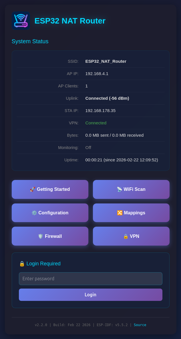
The main dashboard displays:
- SSID and AP IP address
- Number of connected AP clients
- Uplink connection status with signal strength
- STA IP address
- VPN status (when enabled)
- Bytes sent/received
- Monitoring (PCAP capture) status
- Uptime
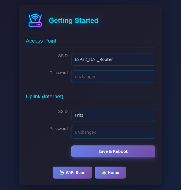
A simplified setup page for first-time configuration:
- Access Point: Set AP SSID and password
- Uplink (Internet): Set upstream WiFi SSID and password
The WiFi Scan page "Connect" buttons link directly to this page with the SSID pre-filled. Click "Save & Reboot" to apply changes.
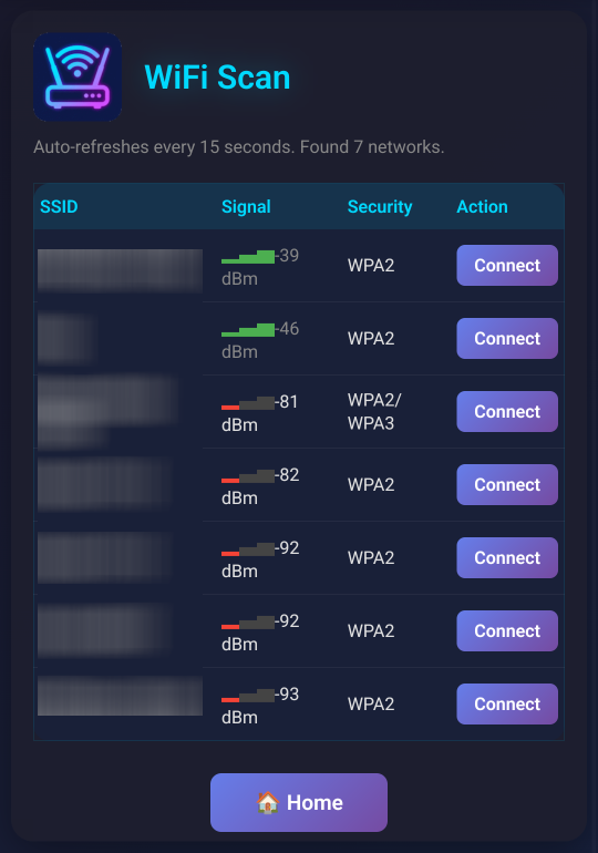
Shows a WiFi network scan and allows for direct connection via the Getting Started page. On ESP32-C5, a channel column with band indicator (2.4G/5G) is displayed for each network.
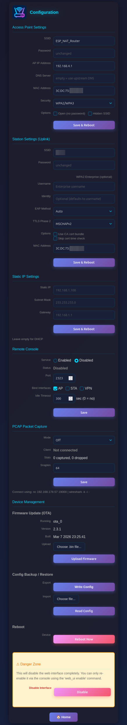
Configure all advanced router settings:
- Access Point Settings: Configure the ESP32's access point name, password, IP address, DNS server, MAC address, and security mode (WPA2/WPA3, WPA2 only, or WPA3 only)
- Station Settings (Uplink): Enter the SSID and password for the upstream WiFi network (leave password blank for open networks), with optional WPA2-Enterprise settings (EAP method, TTLS Phase 2, CA cert bundle, time check), MAC address customization, and band preference (auto/2.4 GHz/5 GHz on ESP32-C5)
- Static IP Settings: Optionally configure a static IP for the STA (upstream) interface
- Remote Console: Enable/disable, port, interface binding (AP/STA/VPN), and idle timeout
- PCAP Packet Capture: Capture mode, snaplen (max bytes per packet), and connection status
- Firmware Update (OTA): Over-the-air firmware updates, running partition, version, and build info
- Device Management: Config backup/restore, reboot, and danger zone (disable web interface)
Be aware that changes to AP settings (including the AP IP address) also affect the config interface itself - after changing the AP IP address, reconnect to the ESP32 at the new IP address to continue configuration. Also all currently defined DHCP reservations and port forwards will be deleted.
The Configuration page includes a Config Backup / Restore section under Device Management:
- Export (Write Config): Downloads a JSON file containing all router settings (WiFi credentials, DHCP reservations, port mappings, ACL rules, etc.)
- Import (Read Config): Upload a previously exported JSON file to restore settings. The device reboots automatically after import to apply the configuration.
This is useful for cloning settings across multiple devices or for backup before a factory reset.
The Configuration page includes an OTA (Over-The-Air) firmware update section:
-
Running: Shows the currently active OTA partition (e.g.,
ota_0orota_1) -
Version: The firmware version (set via
PROJECT_VERin CMakeLists.txt) - Built: Build date and time
To update firmware:
- Build the new firmware with
idf.py build - Navigate to the Configuration page
- In the "Firmware Update (OTA)" section, click "Choose .bin file..." and select the
.binfile from thebuild/directory - Click "Upload Firmware"
- A progress bar shows the upload status
- The device reboots automatically after a successful update
The upload validates the firmware before applying:
- Checks for valid firmware header (magic byte)
- Verifies the firmware is built for the correct chip type (e.g., ESP32 vs ESP32-C3)
- Validates the image integrity after writing
If rollback support is enabled (CONFIG_BOOTLOADER_APP_ROLLBACK_ENABLE=y in sdkconfig.defaults), the new firmware must confirm itself on first boot. If it fails to start, the device automatically rolls back to the previous working firmware.
Note: OTA updates the application firmware only. The bootloader can only be updated via serial flash (idf.py flash).
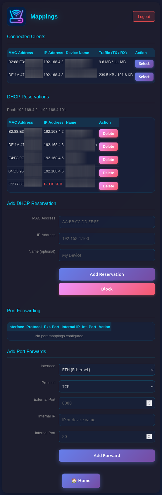
Manage network mappings, i.e. IP addresses via DHCP and ports via port forwarding:
- Connected Clients: Shows all currently connected clients with MAC, IP, and optionally name. Each client has a Reserve button to assign a fixed IP, and a Block button to blacklist the client by MAC address.
- DHCP Reservations: Assign fixed IP addresses to specific MAC addresses (useful for servers/devices that need consistent IPs). Blocked clients show BLOCKED in red. Make sure you assign port numbers in the range of the DHCP pool.
-
Port Forwarding: Create port mappings to access devices behind the NAT router (e.g.,
TCP 8080 -> 192.168.4.2:80). Each mapping can be bound to the STA (upstream WiFi) or VPN (WireGuard tunnel) interface.
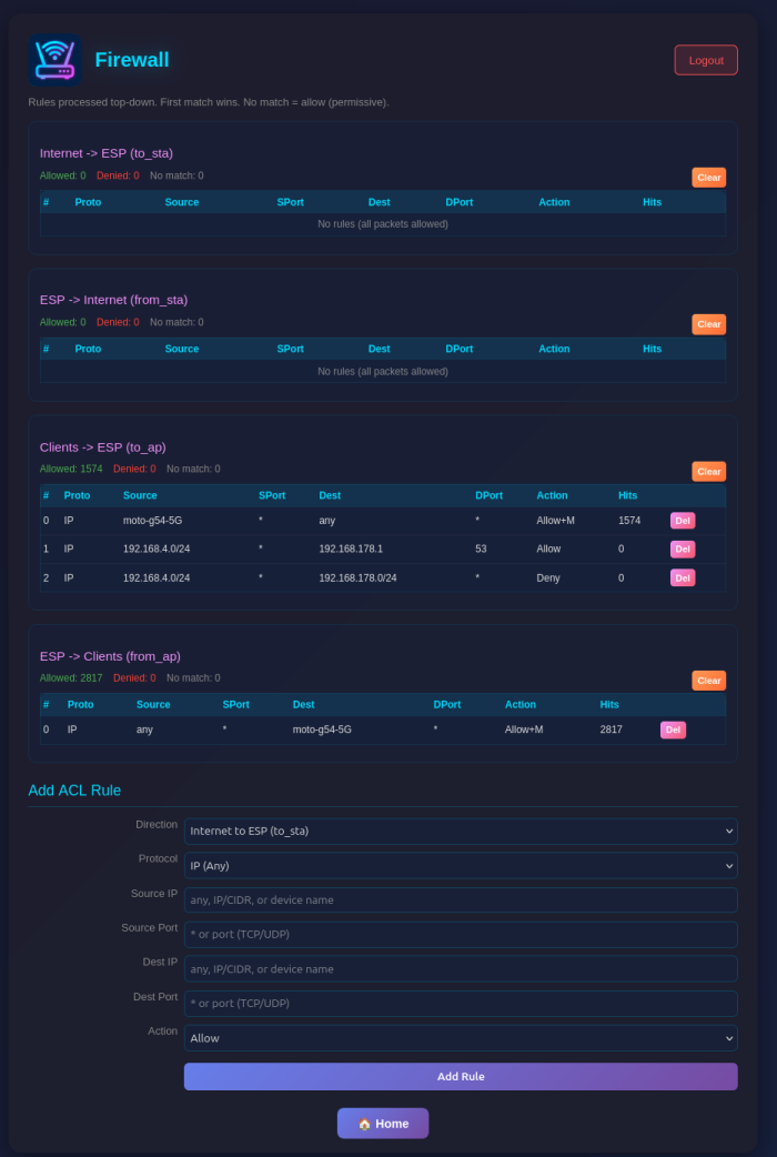
Configure Access Control Lists (ACLs) for packet filtering:
- Four ACL Lists: Control traffic in each direction (to_esp, from_esp, to_ap, from_ap)
- Rule Management: Add rules with protocol, source/destination IP, ports, and action (allow/deny)
- Device Names: Use device names from DHCP reservations instead of IP addresses for single-host rules
- Monitoring: Enable packet capture for specific rules with the Monitor flag
- Statistics: View hit counters for each rule and overall ACL statistics
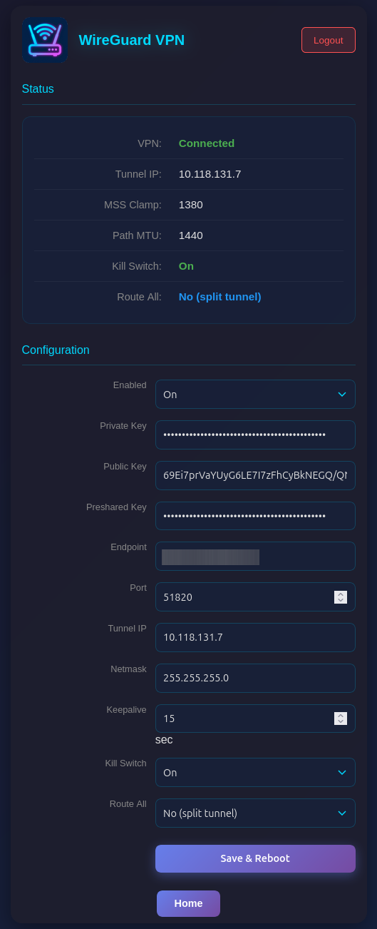
Configure WireGuard VPN tunnel for upstream traffic:
- Status: Connection state (Connected/Handshake Pending/Disconnected), tunnel IP, MSS/PMTU values
- Configuration: Enable/disable, private key, public key, preshared key (optional), endpoint, port, tunnel IP, netmask, keepalive
When VPN is enabled, all NATed traffic from AP clients is routed through the WireGuard tunnel. MSS clamping (1380) and Path MTU (1440) are automatically applied. The VPN auto-reconnects when the STA interface goes down and comes back up.
The web interface is visible on both interfaces (AP and STA) and allows configuration access to all parameters. Two security mechanisms are available:
You can protect the /config and /mappings pages with a password. The main status page (/) remains accessible but will show a login form.
Setting a Password (Web Interface):
- On the main page (
/), scroll to the "Set Password" section - Enter and confirm your new password
- Click "Set Password"
- The page will reload and show a login form
Setting a Password (Serial Console):
set_router_password mypassword
To disable password protection, set an empty password:
set_router_password ""
When password protection is enabled:
- The main page shows system status and a login form
- After successful login, you can access
/configand/mappings - Sessions expire after 30 minutes of inactivity
- A "Logout" button appears on all pages when logged in
For maximum security in open environments, you can completely disable the web interface:
From the Web Interface:
- Navigate to the
/configpage - Scroll to the "Danger Zone" section at the bottom
- Click "Disable" button
- Confirm the warning dialog
- The device will reboot with the web interface disabled
From the Serial Console:
web_ui disable
After disabling, the web interface will be completely inaccessible. Re-enable it via the serial console with:
web_ui enable
If you made a mistake and have lost all contact with the ESP you can still use the serial console to reconfigure it. All parameter settings are stored in NVS (non volatile storage), which is not erased by simple re-flashing the binaries. If you want to wipe it out, use "esptool.py -p /dev/ttyUSB0 erase_flash".